number4
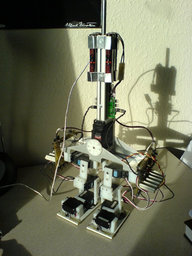
number4point1 - the current version

Main goals are a body, a new electronic and more sensors. The new electronic boards for the legs are already working. The sensors at the foots are added and calibrated.
Documents

Some older articles for reference:
Graphics
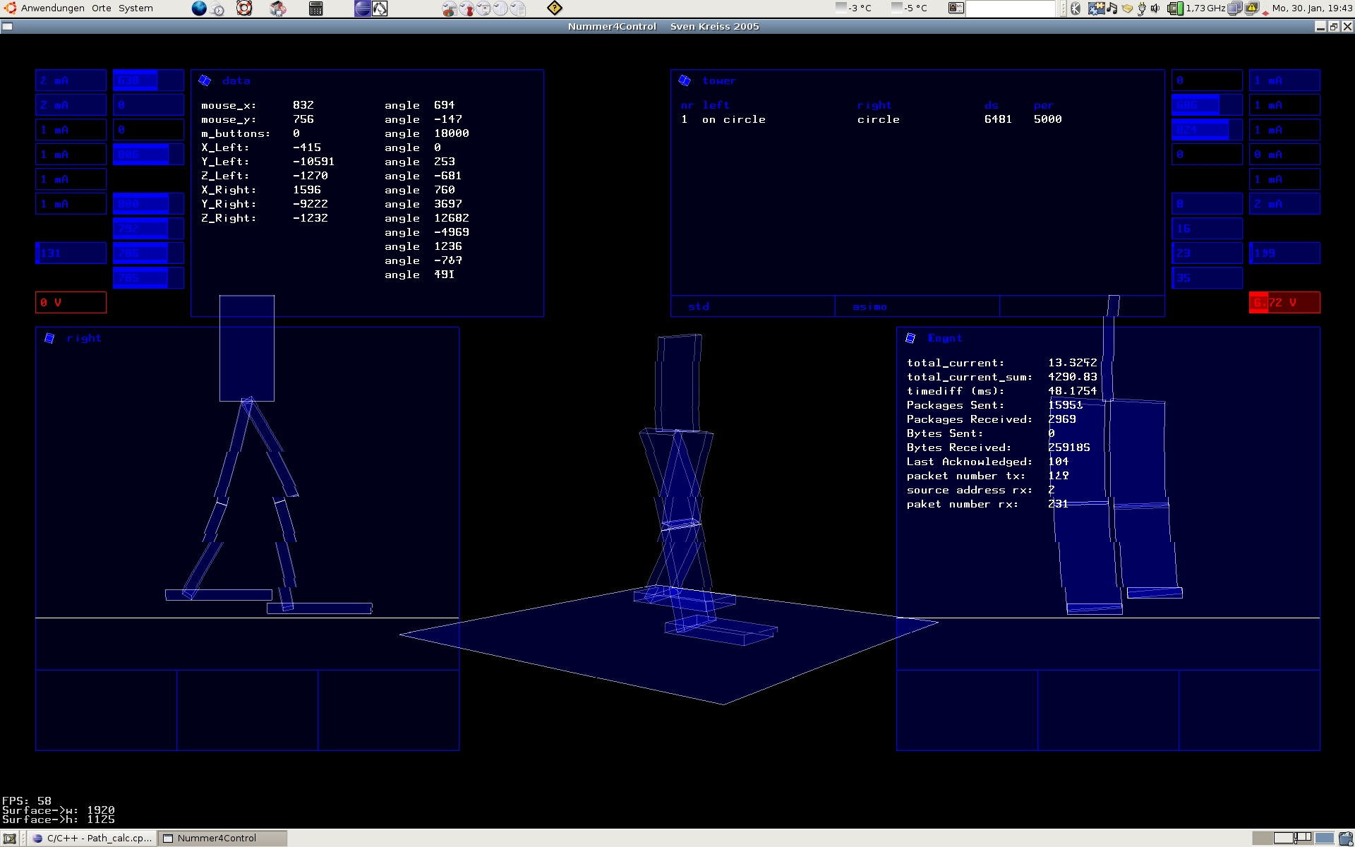
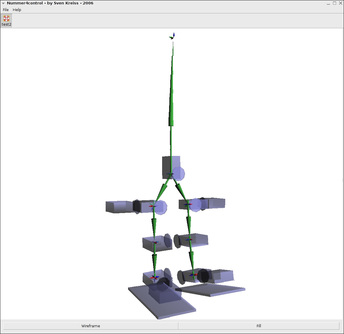
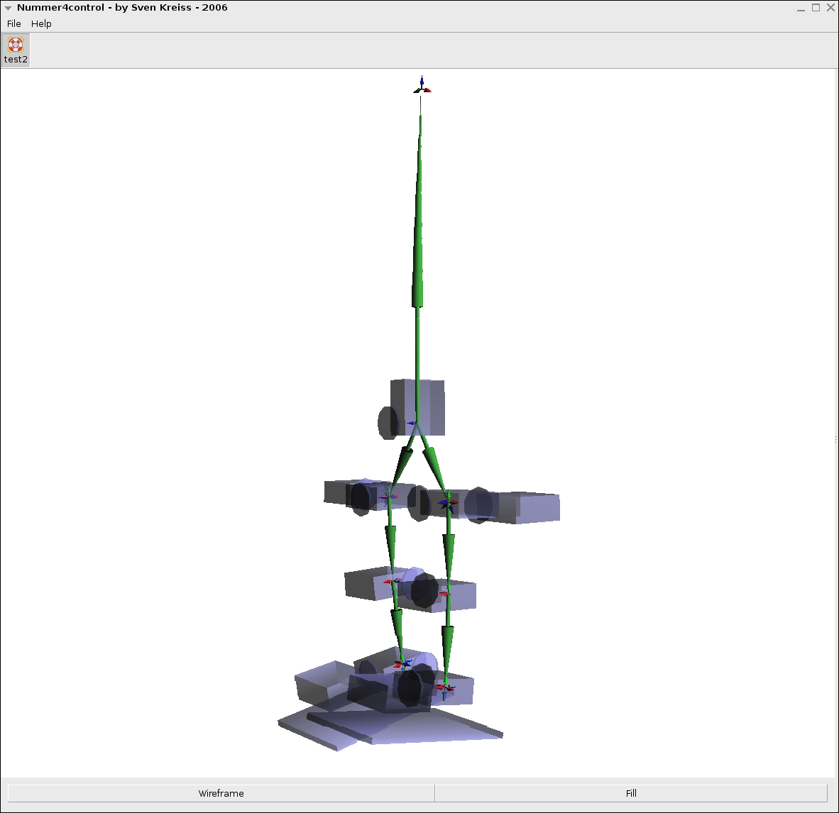
Just want to put up some screen shots from one of the OpenGL program that was used as a backend.


Electronic
Emphasize on autonomy, distributed calculations, Hardware-PWM-Generation, current-measurement, Master-Multislave-Bus and a sensor network.
- distributed calculations: Master is a ATMega128, calculates the coordinates of the foots, Slaves (also ATMega128) calculate the angle at the joints from the coordinates
- Hardware-PWM-Generation: at ATMega128, 2x 16Bit-Timer with 3 Capture-Compare-Registers each
- current-measurement: with 6 of the 8 ADC-channels of the ATMega128 the "potential-drop" at a 1 Ohm power-resistor is measured.
- Master-Multislave-Bus: with USART; TX from Master is connected to many Slaves (RX) via RS-485 network (bi-directional); clock signal is transmitted over separate RS-485 bus (single direction)
- Slave-Board: ATMega128 do not have enough spare ADC-Ports, therefore there is an additional ATMega16. This one is connected to the serial bus too. The ATMega16 reads the force sensors, distance sensors and the acceleration sensors.
Force Sensors
The robot has eight force sensors now. Four on each foot. The force is measured with a force-sensitive resistor. It is an element consisting of several sheets of foil with two pins. The resistance between the two pins changes with force on the foil. Without the force there is a resistance of more then 2MOhm. With two fingers one can reduce this resistance down to approximately 2kOhm. One end of the force-sensitive resistor is connected to 5V. The other one to one of the eight ADC-Inputs of the ATMega16 and to a 100kOhm resistor which is connected to ground.